Options for antennas, masts and towers
Antennas play an important role in radio broadcasting. The antenna is the piece of equipment which gets your signal out to the audience you want to reach. Without it, you will only be able to broadcast around 5 ft! This document will explain what you need to know about types of antennas including where and how to mount an antenna.
FCC Regulations on Low Power FM
The FCC has certain regulations a Low Power FM (LPFM) station must follow if they are to broadcast legally. The reasoning behind most them is to avoid interference between stations. Here is a list of rules that must be taken into account if you want to avoid trouble.
The FCC requires:
- Maximum 100 Watts Emitted Radiated Power (ERP) at 30 meters Height Above
- Average Terrain (HAAT).Antenna must be placed 13.5 feet away from any heavily trafficked public areas.
- Low Power FM stations may only use omnidirectional (sometimes called “non-directional”) antennas.
These are the rules as of August 2011. They are subject to change by the FCC. We
recommend staying up to date so that you can avoid unnecessary costs when buying equipment.
Definition of Terms
You might be asking yourself, what do all these terms mean? They are a combination of engineering terms and FCC legal jargon. Spend some time getting familiar with these terms. They will be used extensively throughout the rest of this document and in your FCC application.
Antennas – usually consist of a rigid metallic structure. The antenna radiates the signal produced by an FM transmitter. Different antennas will result in different coverage areas for your station.
There are 2 types of antennas:
- Directional – focuses the radiated radio wave in a particular direction.
- Omnidirectional – radiates radio waves in all directions.
Towers/Masts – are used to hold up an antenna up. A mast is generally a single pipe and is often mounted on a roof or other structure, while a tower consists of a set of interlocking pipes, which can be taller and is usually built from the ground.
Polarization – refers to orientation of the radiated electric field by the antenna. In other words, it identifies the direction in which the radiated waves will propagate off an antenna. The structure and orientation of the antenna determines what type of polarization occurs. Radio reception is clearest when the transmitting antenna and the receiving antenna have the same polarization.
There are 3 types of polarization:
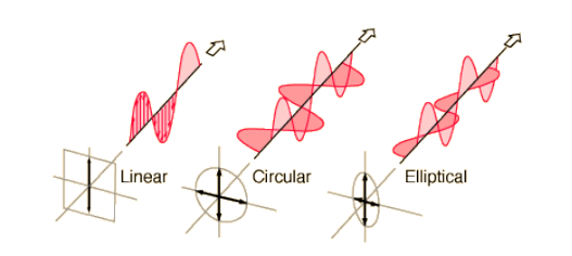
- Linear – radiates signals in the Horizontal or Vertical plane.
- Circular – radiates all signals equally in Horizontal and Vertical plane.
- Elliptical – radiates signals in the Horizontal and Vertical plane, with more power in one than in the other.
Transmitter Power (TPO) – is the power in Watts (W) the FM transmitter is using to output a radio signal to the antenna.
Antenna Power – is the power delivered to the antenna. This will be less than the TPO because some energy is lost in the the cables that run from the transmitter to the antenna. For example, if the transmission line is 80% efficient (a typical efficiency) and the TPO is 100 Watts, the antenna power will be 80 Watts.
Antenna Power Gain – is the change in power that results when the antenna focuses the power in a particular direction. A gain of 2 means the signal in the strongest direction from the antenna will be twice as strong as the signal coming into the antenna.
Effective Radiated Power (ERP) – is the final power output from your antenna, which is used to predict the broadcast range of your radio signal. It is defined as:
ERP = [Antenna Power] X [Antenna Power Gain]
Since both the vertical and horizontal polarized components contribute to the broadcast range, the FCC mandates that neither component can exceed 100 ERP.
Height Above Average Terrain (HAAT) – refers to the antenna height relative to the region’s “average terrain”. The FCC calculates the HAAT by estimating the average altitude in an area near the antenna site, and subtracting that from the height of the antenna. You can calculate the HAAT for a particular location using the calculator at:
➔http://transition.fcc.gov/mb/audio/bickel/haat_calculator.html.
To Plan or Not to Plan?
Planning out an antenna site can require extensive work. You may even need to hire an engineer to get the best signal coverage. Without adequate planning, a number of factors can cause interference to the broadcast signal.
Here is a brief list of things you should consider when planning:
- FCC Regulations on LPF
- Transmitter Power and Antenna Power Gain
- Polarization of Antennas
- Regional Geography/Topography
- Nearby Antennas
Sophisticated planning takes into account many details about wave propagation such as refraction, reflection, depolarization, diffraction, absorption, scattering, Fresnel zone clearances, beam tilt, null areas, grazing and Brewster angle problems. Although all these factors affect the broadcast signal, you don’t need to calculate them to broadcast a basic signal. With a signal detector, some adjustments and some patience, you can get your signal to your target audience. Still, we need to keep in mind the FCC regulations that are in place for antennas.
Analysis of Antennas
An antenna gets a radio signal from a transmitter. The signal usually comes through a piece of cable called a transmission line. The antenna then converts this signal into a radio wave which radiates in free space.
Frequency and Wavelength
FM Radio waves operate at the lower end of the electromagnetic band along side with TV and AM radio. The FCC designates the section of the band from 88 mega-hertz (Mhz) to 108 mega-hertz for FM broadcast.
Radio waves at these frequencies are around 3 meters in length. This measurement is referred to as the wavelength. Wavelength is inversely proportional to frequency. In other words, if you increase the frequency, it will cause the wavelength will decrease and vice versa.
For example, imagine a loaf of bread 300,000 kilometers long. If it is cut into 1,000,000 slices, each slice will be 300 meters thick; if it is cut into 300,000,000 slices, each slice will be 1 meter thick. In exactly the same way, a frequency of 1 Mhz will have a wavelength of almost 300 meters; for a signal of 300 Mhz, the wavelength is 1 meter.
[insert Fig 2.2]
Most antennas for FM radio are “quarter-waves” antennas, meaning that they work best when they’re one quarter of a wavelength long. The frequency an antenna works best at is referred to as the resonance frequency. Some antennas come pre-tuned to a particular resonance frequency, while others are adjustable within a certain range of frequencies.
Signal Propagation
The antenna broadcasts radio waves, with a particular radiation pattern. The radiation
pattern determines where the signal from the antenna will be strongest.
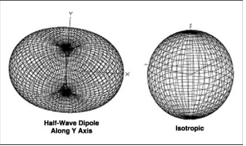
The radiation pattern is determined by that antenna’s gain. Picture an antenna that radiates equally in every direction. If you imagine a sphere centered around that antenna, the signal strength will be the same anywhere along the sphere.
This antenna is referred to as an isotropic radiator. Although it is physically impossible to make an isotropic radiator, it helps us analyze other radiation patterns. Real signals differ in power as they radiate from the source and the difference in power between real and isotropic can be a useful comparison. If the intensity of the signal is reduced in some directions, then it will increase in other directions.
The intentional focusing of power of the radiated signal like this is called gain. Gain is sometimes measured with a multiplier. An isotropic radiator has a gain of 1. If an antennas has a gain of 2, that means the signal strength in the strongest direction is twice as strong as it would be in an isotropic antenna. Sometimes gain is measured in decibels(dB) instead. A 0dB gain is equivalent to a multiple of 1, and every gain of 3dB is equivalent to double the power in the strongest direction. Antenna gain doesn’t mean that an antenna is stronger overall, it just means the power is focused in a certain direction.
A directional antenna is an antenna that has high gain in a particular direction.
Directional antennas are useful when you only want to reach a particular location. Radio stations sometimes use directional antennas for a link to send their signal from the studio to the transmitter.
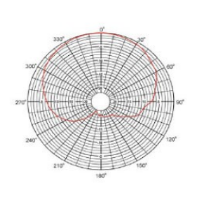
Illustration 1: An directional antenna pattern
Currently, LPFM stations are only allowed to use omnidirectional antennas, although thismay be subject to change. An omnidirectional antenna is one that has the same power in every direction along the earth’s surface. This is different from an isotropic antenna because it may radiate more power in the horizontal than in the vertical direction.
The energy, or signal strength, is strongest near the antenna and reduces as you get farther away from the antenna. The same amount of energy is distributed over an increasingly larger area, thereby reducing signal strength.
Radio wave propagation depends both on the radiation pattern and the environmental conditions between the transmitting and receiving antennas. Certain conditions will cause signal interference:
- Buildings or obstructing structures
- Hills or mountains
- Forests or dense foliage
All these obstacles will contribute to either an absorption or reflection of the radio signal.
A good rule of thumb is your signal will propagate best to any location you can see from the antenna.
[figure 2.6 In big book]
Polarization
The polarization of the antenna determines the dimension in which the radio wave propagates in, either on the horizontal or vertical plane. Although radio reception works best when both the receiving and transmitting antenna have the same polarity, you will still be able to communicate with each the at the cost of a reduced signal strength. Generally car radio antennas are vertically polarized, but home radio antennas are often horizontally polarized. We recommend using a circularly polarized (CP) transmitting antenna. As mentioned earlier, a CP antenna radiates both vertically and horizontally polarized signals, so it will provide uniform reception to home and car radios.
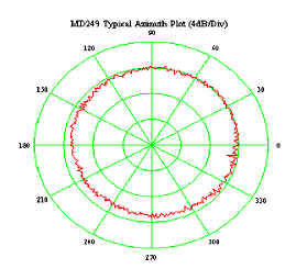
Illustration 2: An omnidirectional antenna pattern
2 Bay or not 2 Bay?
Because circularly polarized antennas split the power between the horizontally polarized and vertically polarized parts of the signal, they have a low gain (usually around 0.5). However, if you stack 2 circularly polarized antennas one on top of the other with the right spacing in between, the gain of the antennas will add together. This is called a 2-bay antenna system. A 2-bay CP antenna system will have a gain around 1. A single-bay CP system will need around 240 watts of transmitter power(TPO), because about 40 watts will be lost on the way to the antenna and the rest of the power will be split between the vertical and horizontal signals. A 2-bay CP system will only need about 120 watts TPO for the same ERP.
The main disadvantage of using a 2-bay antenna system is it requires more space on the tower. However, if you have the space, we recommend using a 2-bay system, because the cost of a second antenna is generally less than the added cost for a higher-powered transmitter and you’ll also save power!
For more details on equipment costs, see the Prometheus Low Power FM Radio Equipment Guide at:
➔ http://www.prometheusradio.org/sites/default/files/Prometheus_Equipment_Guide.pdf
Antennas for FM Broadcasting must be chosen carefully in order to cover the service
areas properly with adequate level and quality signals. For economic and technical reasons, the desired economic power (ERP) should be produced with a balance between antenna gain and transmitter power. For example, if you plan on running your station on solar power or other renewable energy sources, you would probably prefer a lower TPO. The height of the antenna over the service area, distance to areas of population, ERP, and economics are items that must be considered.
Location, Location, Location
When considering where to place an antenna, you need to identify the geographical conditions around the broadcast area.
Ask yourself:
- Are there any nearby mountains?
- Are there any nearby buildings/structures?
- Are there any nearby antennas?
- What does your regional topography consist of?
Radio waves are subject to conditions such as reflection. If your antenna is placed in such a way such that the reflected radio waves off a nearby mountain/structure are directed to your broadcast area, then there can be an area where the broadcast signal and the reflected signal cancel each other out. This condition is referred to as multipath interference. These canceled out signals will make it difficult for people in that area to tune into your station. Proper placement of your antenna can minimize or even eliminate this area.
To avoid multipath interference:
- Avoid nearby hills or mountains
- Avoid structures in the immediate vicinity of the antenna
It is very important you survey the area for possible interference! Selecting a site that has other radio equipment (TV transmitters, cell phone stations, amateur radio equipment, etc) often
requires a study by a radio engineer. You want to make sure that your new 100 watt transmitteris not the “straw that broke the camels back” which puts the site over the legal limit for radio radiation exposure to the public.
Another consideration is whether you will interfere with the other equipment, or the other equipment will interfere with you. The engineer of the tower will probably be able to make a good educated guess at the potential for interference between the different equipment on the tower. Interference between equipment that operates on different bands is unlikely, but not impossible, especially if some equipment is at much greater power than others and the antennas or transmitters or feed lines are very close to each other.
Antenna Placement
The process behind antenna placement is unique to your region and community. There is no one universal formula for the best radiation pattern at any point in the world. Therefore, you need to survey your area carefully, identifying possible locations, taking notes on how to get the best signal coverage at an economic cost your community can afford. Ask around the community as well, maybe some one who is interested in contributing to the station will be willing to donate their property for the community!
The best solution for antenna placement is to have a structure that is already tall, since making tall things from scratch is usually more involved. Look around for church steeples, old ham radio towers, bridges, billboards…anything tall. Keep in mind that if you find yourself placing an antenna above 30 meters HAAT, you must reduce your ERP accordingly. The FCC has a tool which can calculate the required adjustments.
➔ http://transition.fcc.gov/mb/audio/bickel/fmpower.html
In most cases your coverage will be better with a 100 W ERP at 30 m HAAT than with reduced power at a higher location, so try to mount your antenna as close to 30 m above average terrain as possible, unless you need to mount higher to clear nearby obstacles.
The following is a list of places to consider in your surveying process:
- Water Towers – Common structure in a town but historical and aesthetic concerns
sometimes preclude this option. You can mount an antenna at the top of the tower or
mount the antenna at the legs of the tower. - Utility Poles – Road or railway ‘right of way’ poles are common, but might require a permit to use. Make sure the pole is buried in a hole in the ground that is 10% of their length.
- Towers – Can be tall and fairly light for an LPFM, but finding a suitable site can be difficult. Towers can be rented to other stations to cut costs.
- Flagpoles – Many counties across the country have moratoriums on the construction of towers, but there are few places that would prevent the construction of flagpoles. Consult with locals to construct a new flagpole where you can mount antenna on top.
- Trees – A tree can work if it is the tallest structure available,but be aware that since leaves hold a lot of reflective surface, the proximity to the leaves of the tree to the antenna can significantly throw off your antennas signal.
- Telescoping masts are used to support any antenna pole placement by using guy wires, turnbuckles and other hardware. They can be installed on the ground or on the top of a building. Check your local legislation to see if you are required to have a permit for any type of mast.To add stability, it is good to get a tripod or a heavy-duty section of mast for the bottom.The guy wires will need to be anchored to the roof or the ground at a distance of at least 60% of the height of the pole, spread out as equidistantly as possible in usually 3 or occasionally 4 directions. A rule of thumb says you need twice the height of the pole in distance from the base of the pole to any power lines.
Survey the area carefully so if the pole ever were to fall, it would not hit a power line!
Another rule to remember is you should have tie points for the guy wires in three equally spaced directions, at 60% of the total height of the pole. For a 36-foot pole, that would be about 20 feet. You can fudge this a little bit to fit on your roof, but not too much!
Ideally, the antenna should be about one wavelength from any other object (except for the pole it is mounted to). There will be reflections even off of a slender pole, and radio energy will be dampened in the direction of the obstruction.
~Important Things to Consider~
- You need to be able to get at the antenna to make occasional adjustments. It is cheaper to put up a fixed tower, but one you can raise and lower may be a good investment if you have to work on it a lot.
- Is it climbable? Towers that can support human weight up at the top are definitely a bit more complicated than your basic antenna pole.
- Is the tower site accessible to a crane or a cherry picker?
Lightning Protection and Grounding
What are the chances your tower will get hit by lightning? Not bad. Remember the chance of getting hit by lightning is absurdly small when you are on the ground, but as you get to be the tallest thing for a few thousand feet around, your chances get much higher. Installing a lightning arrestor at the base of your antenna will help prevent (or at least lessen) damage from lightning. A direct hit by lightning will probably destroy your antenna and any equipment connected to it, even if you use a lightning arrestor. This is a good reason to mount your antenna a few feet below the top of the structure it is on, so it’s not the highest thing around. However, a nearby lightning strike can also cause electrical spikes in the antenna and transmission line. A lightning arrestor can protect your equipment from harm in these less direct hits.
It’s also important to connect your antenna to the ground to allow built-up charges to drain. This will keep the antenna operating as efficiently as possible. A good ground system might consist of an 8′ copper stake in the ground and a copper ribbon or thick braided copper wire running directly up to the antenna. The effectiveness of a ground system depends on the conductivity of the soil at your site, the surface area of the object driven into the ground, and the thickness of the wire or ribbon running from the ground to the antenna.
Word of Advice: Starting Small Is Better Than Not Starting!
Many stations flounder because they wait to build the tallest thing possible to start. We encourage groups to go ahead and put up a short pole now, and wait for the big tall tower until
later. A tower built from scratch can cost many tens of thousands of dollars and cause many zoning delays, etc.
If you have a small core group and not much money, a tower can be a very daunting task. It is best to put something up quickly with the small resources the few of you can muster. Focus on gaining the support of the community and get everyone started doing their show, and then you will have a much larger group to work together to tackle the task of building the tower.
If you are clearing the rooftops of most other buildings around you by at least 20 feet, you will go farther than you expect. That may be enough to get you going and to pull your community in the doors. You will be amazed by what they might come up with that can save you a lot of headaches!
Where to Get More Information
This document will help you start planning your antenna site, but at some point you will probably need more information. We recommend looking around for a local engineer who can advise your station for free or at a reduced cost. They can do a check of your plans and supervise the installation process. Never climb towers or work with radio frequency electronics without someone who has climbing or electrical experience!